Instrument Settings
The following settings are saved to the device memory and will not change if the sensor type is changed.
| 1. | Scroll to Settings. |
| 2. | Select Instrument. |
| 3. | Select to enter the menu. |
Table 12 Default Device Settings
Setting |
|
Default |
Menu 1 Options |
Menu 2 Options |
|
Relay Setup
|
Relay State |
De-energized (Fault Relay always energized) |
Relay 1 Relay 2 |
De-energized Energized
|
|
Mapping |
Common |
Relay 1 Relay 2 |
Common Discrete Horn |
|
|
Analog Settings (see Table 13 ) |
Custom 1 (see Table 13 ) |
3.5mA with HART 1.25mA with HART Custom 1 Custom 2
|
Custom Settings Calibration Cleaning mode1 Fault Maintenance
|
|
|
Cal Alert |
Disabled |
Enable Disable |
(none) |
|
|
Bluetooth |
Enabled |
Bluetooth Status Reset All |
Enable Disable Reset All |
|
|
Min/Max/Avg |
1h |
Interval (1h, 8h, 24h) Start Hour (0-23h) |
|
|
|
Swap Delay |
Enabled |
Enable Disable |
|
|
|
Set Date
|
UTC-5(Factory Date and Time) |
Year (2000-2999)Month (Jan-Dec)Day (0-31)Time (0:00-23:59) |
|
|
|
Password
|
Disabled |
0000-9999, incr. 0001 |
|
|
|
Controller Data Reset |
N/A |
Controller Data Reset |
|
|
|
Display Units
|
Sensor Dependent (see Table 14 ) |
PPMmg/m3µMol%Vol |
|
|
|
Tag #
|
Blank |
Only configurable via HART and Bluetooth |
|
|
|
Reset Main Unit |
N/A |
Reset Main Unit |
|
|
1 Cleaning mode not available
Setup Relay State for Energized or De-Energized
Relays 1 and 2 are default De-energized. Relay 3 is a fault relay that is set to Energized and cannot be changed.
To set Alarm Relay State:
| 1. | Scroll to Settings. |
| 2. | Select Instrument. |
| 3. | Select Relay Setup. |
| 4. | Select Relay State. |
| 5. | Select Relay 1 or Relay 2. |
| 6. | Select Energized or De-Energized. |
Relay Mapping
Relay 1 and Relay 2 can be configured for common, discrete, and horn modes via the device display menu or X/S Connect app. Common mode is the default relay mapping setting. In Common mode, Relay 1 is actuated by Alarm 1 on either sensor, and Relay 2 is actuated by Alarm 2 on either sensor.
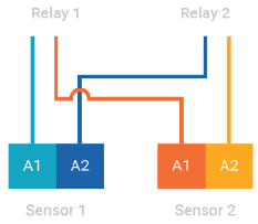
Figure 37 Common Mode Relay Map and Alarm Actuation
Discrete mode allows a separate action for each sensor. Relay 1 is actuated by Sensor 1 alarms and Relay 2 is actuated by Sensor 2 alarms.
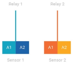
Figure 38 Discrete Mode Relay Map and Alarm Actuation
Horn mode is designed to allow local acknowledgment of a relay-triggered horn, while the alarm state is still present. All alarms on both sensors trigger both relays, however the second relay can be acknowledged by pressing one finger over each of the EZ touch buttons and holding for 1 second before releasing.
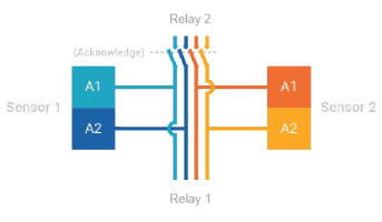
Figure 39 Horn Mode Relay Map and Alarm Actuation
Analog Output Settings for Fault Conditions
Analog outputs can be set to 3.5 mA and 1.25 mA with HART, or to custom output values as listed in Table 13 . Output settings for oxygen sensors are not configurable. The Maintenance analog output is used during start up, Reset Main Unit, and Controller Data Reset.
To change Analog outputs settings:
| 1. | Scroll to Settings. |
| 2. | Select Instruments. |
| 3. | Scroll and Select Analog Settings. |
| 4. | Select 3.5, 1.25, Custom 1 or Custom 2. |
| 5. | Select Save. |
| 6. | (Only Custom) Select Fault, Calibration, or Maintenance. |
| 7. | (Only Custom) Enter desired output levels (options in Table 13 ). |
| 8. | (Only Custom) Select Save. |
| 9. | (Only Custom) Repeat for remaining outputs. |
| 10. | Select Save. |
Table 13 Analog Output Setting Options
Output Setting (mA) |
3.5 mA |
1.25 mA |
Custom 1 Default1 |
Custom 2 Default |
Fault Relay Action |
AO Range Options |
|---|---|---|---|---|---|---|
|
Fault |
3.52 |
1.252 |
2.0 |
2.0 |
Open, Latching |
Range: 0.000-3.750 Increment: 0.025 |
|
Calibration Mode (excl. O2) |
3.52 |
1.52 |
3.0 |
3.0 |
Closed, No Action |
Range: 0.000-3.750Increment: 0.025 |
|
Cleaning Mode (NOT ENABLED) |
3.52 |
2.02 |
2.5 |
2.5 |
Closed, No Action |
Range: 0.000-3.750Increment: 0.025 |
|
Maintenance |
3.52 |
3.52 |
3.5 |
3.5 |
Closed, No Action |
Range: 0.000-3.750Increment: 0.025 |
|
O2 Calibration Mode |
3.52 |
1.52 |
21.73 |
Same as Calibration |
Closed, No Action |
Range: 0.000-3.750Increment: 0.025 |
|
Cal Alert |
3.5 |
3.0 |
3.0 |
3.0 |
Closed, No Action |
Range: 0.000-3.750 Increment 0.025 |
|
Zero Reading |
4.042 |
Closed, No Action | ||||
|
Over Range |
21.72 |
Closed, No Action |
1 Default factory setting
2 Not configurable
3 For an O2 sensor, 21.7 mA is the default Custom 1 setting and is not configurable.
Calibration Alert
XCell H2S and CO sensors with TruCal technology actively monitor sensor and adjust sensitivity without any manual intervention. When equipped with Diffusion Supervision, TruCal will also monitor the sensor inlet for obstructions while Diffusion Supervision is enabled. These sensors do not need to be calibrated on a static maintenance cycle. When a manual calibration is recommended, the sensor will detect this and slow flash either the left green LED or right green LED indicating that calibration is recommended for sensor 1 or sensor 2 respectively. Users can also enable Calibration Alert so that an analog output signal is sent to the control room when a calibration is recommended. Whether or not the calibration alert is enabled, if gas is detected by the sensor, the ULTIMA X5000's analog output and display will follow the gas reading.
To Enable Calibration Alert:
| 1. | Scroll to Settings. |
| 2. | Select Instrument. |
| 3. | Scroll and select Cal Alert. |
| 4. | Select Enable Cal Alert. |
| 5. | Scroll and select Save. |
Enable Bluetooth Communications
Every ULTIMA X5000 ordered with Bluetooth comes with the communications enabled by default. Bluetooth must be enabled for any Bluetooth functions to operate. A compatible Bluetooth host with the X/S Connect App is needed for connection.
To disable Bluetooth:
| 1. | Scroll to Settings. |
| 2. | Select Instrument. |
| 3. | Scroll and select Bluetooth. |
| 4. | Select Bluetooth Status. |
| 5. | Select Disable. |
| 6. | Select Save. |
|
Devices ordered without Bluetooth do not contain a Bluetooth chip, but may show Bluetooth as a menu option. On these devices if a user tries to enable Bluetooth, it will appear as though the enable setting is not being saved. Check the product configuration. If the third value is a non-zero value, it may be ordered without Bluetooth. |
Bluetooth Pairing
The instrument memory has the ability to store up to 25 mobile devices in its memory.
As a visual indication, the green LEDs will toggle and quickly flash when a device is paired.
Once paired with an X5000, the user will be able to connect to the same X5000 remotely and without needing to enter a pairing code, unless over 25 other devices are paired with the same X5000 afterwards.
To pair with the X5000:
| 1. | Download the X/S Connect App from the Google Play Store or the iOS App Store. |
| 2. | Open the X/S Connect App. |
| 3. | Select “Connect” for the X5000 that you would like to connect with. |
| 4. | (First Time Only) When prompted, tap EZ touch button to display a 6-digit pass code. |
| 5. | Enter Pairing Code shown on X5000 display. |
Bluetooth Security
The Bluetooth connection is encrypted and secured with a unique six digit pin that must be confirmed on the mobile device and acknowledged on the detector display. All of the previously paired devices can be erased from the X5000 to provide additional security and control.
To Reset All device pairings:
| 1. | Scroll to Settings. |
| 2. | Select Instrument. |
| 3. | Scroll and select Bluetooth. |
| 4. | Scroll and select Reset All. |
| 5. | Select Continue. |
Notice
Reset All will delete all paired device memory. All devices will have to re-initiate pairing at the device.
Bluetooth Tag ID
See Status Menu to view Bluetooth Tag ID.
Min/Max/Average
The minimum, maximum, and average gas readings can be set for a user-defined interval. For example, if the interval is set to 24 and the start hour is set to 6, the Min/Max/Avg values will update every 24 hour period starting at 6 am.
The default interval is set to 1h and start hour is 0. The Interval and Start Hour are driven by the Time and Date of the transmitter.
To change Min/Max/Average interval and time:
| 1. | Scroll to Settings. |
| 2. | Select Instrument. |
| 3. | Scroll and select Min/Max/Average. |
| 4. | Select Set Interval. |
| 5. | Enter Interval (1h, 8h, 24h) and Save. |
| 6. | Scroll to Set Start Hour. |
| 7. | Enter Start Hour (0-24h) and Save. |
|
The Min/Max/Average values are only viewable through the X/S connect app or HART. |
Swap Delay
Swap Delay allows the user a brief window to change an XCell sensor without the device going into a fault condition. Once a sensor is disconnected from the transmitter, the user will have 2 minutes to reconnect a sensor. During this time, the device analog output will go to its Maintenance level. If a sensor is reconnected or replaced during the 2 minute window, the new sensor’s countdown sequence will begin and the analog output will remain at the Maintenance level. After the sensor countdown is complete, the analog output will return to reporting a live gas reading. If a sensor is not reconnected after the 2 minute window, the ULTIMA X5000 will enter a “Sensor Missing” fault condition. All XCell Sensors have SafeSwap and do not need to be disconnected from power while changing sensors. For more details on how to change sensors, see Replacing an XCell Sensor. Swap Delay is enabled on all ULTIMA X5000 transmitters by default.
Notice
The transition to maintenance mode during the 2 minute Swap Delay window and sensor countdown will not trigger the Fault Relay. The Fault Relay will only be triggered when the device enters a fault condition.
To enable or disable Swap Delay:
| 1. | Scroll to Settings. |
| 2. | Select Instrument. |
| 3. | Scroll and select Swap Delay. |
| 4. | Select Enabled or Disabled. |
| 5. | Select Save. |
Time and Date Setup
Time and date are set at the factory in GMT. When selected, the current date is displayed. Select Change to edit date and time. The user must save to move onto the next date setting. The Min/Max/Average settings are driven by the date and time and should be changed to local time for data accuracy.
To change Time and Date:
| 1. | Scroll to Settings. |
| 2. | Select Instrument. |
| 3. | Scroll and select Set Date. |
| 4. | Scroll and Select Change. |
| 5. | Select Year and Save. |
| 6. | Select Month and Save. |
| 7. | Select Day and Save. |
| 8. | Set Time and Save. |
|
You can also use the X/S Connect App to sync time and date with a mobile device. |
Enable Password
Enabling password will require the user to enter the password before entering any of the settings menu. The password entry screen defaults to 0000 and is disabled by default.
NOTE: In order to maintain compliance to 60079-29-1, the password must be enabled and set to a non-default value. In addition, an access barrier must be implemented for Modbus and HART communication to prevent parameter changing by unauthorized persons.
When the password is enabled, a lock icon will appear in the top right corner of the display.
If the password is lost, call MSA Customer Service at 1-800-672-2222.
To enable the password:
| 1. | Scroll to Settings. |
| 2. | Select Instrument. |
| 3. | Scroll and select Password. |
| 4. | Select Enable Password. |
| 5. | Scroll and select Save. |
| 6. | Confirm the Password (password is default 0000 until changed). |
Change Password
A password can be changed whether or not the password is enabled.
If the password is lost, call MSA Customer Service at 1-800-672-2222.
To change the password:
| 1. | Scroll to Settings. |
| 2. | Select Instrument. |
| 3. | Scroll and select Password. |
| 4. | Select Change Password. |
| 5. | Enter desired password. |
| 6. | Select Save. |
| 7. | Scroll and select Save to confirm password. |
Language
The ULTIMA X5000 main display can be viewed in multiple languages. Available Languages are: English, French, Spanish, Portuguese, Italian, Dutch, Russian, Chinese, and German.
The X/S Connect App is only available in English, and does not change when the display language on the ULTIMA X5000 is changed.
To change the display language:
| 1. | Scroll to Settings. |
| 2. | Select Instrument. |
| 3. | Scroll and select Language. |
| 4. | Select English, French, Spanish, Portuguese, Italian, Dutch, Russian, Chinese, or German. |
| 5. | Scroll and select Save. |
Controller Data Reset
Controller Data Reset will reset all of the settings in the main PCBA to their factory defaults and cycle power to the unit.
To reset data to factory default values:
| 1. | Scroll to Settings. |
| 2. | Select Instrument. |
| 3. | Scroll and select Controller Data Reset. |
| 4. | Select Continue. |
The unit will reboot, and the analog output will go to the values entered for Maintenance.
Display Units
The default display units are dependent on the sensor type. See Tab 9 for default sensor units. Only % LEL is available for combustible sensors. Only % is available for oxygen sensors.
To change display units:
| 1. | Scroll to Settings. |
| 2. | Select Instrument. |
| 3. | Scroll and select Units. |
| 4. | Select PPM, mg/m3 or μMol. |
| 5. | Scroll and select Save. |
Tag Number
Displays current tag. Default is blank. Below are the valid characters one can enter to identify their unit. Entering the tag is only available via the X/S Connect App and HART. When changed, this will be the name used by the transmitter for advertising Bluetooth signal.
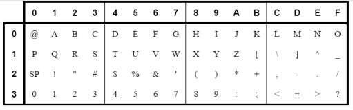
Figure 40 Valid Characters
Reset Main Unit
Reset Main Unit will cycle power on the instrument, without changing any of the settings.
To reset the main unit:
| 1. | Scroll to Settings. |
| 2. | Select Instrument. |
| 3. | Scroll and select Reset Unit. |
| 4. | Select Continue. |
The unit will reboot, and the AO will go to the values entered for Maintenance.